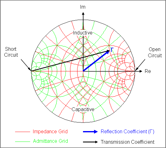

Upper Saddle River, New Jersey: Pearson Education, Inc. This article incorporates public domain material from the General Services Administration document: "Federal Standard 1037C".Reflections of signals on conducting lines.It is most often measured at the transmitter side of a transmission line, but having, as explained, the same value as would be measured at the antenna (load) itself.Īcousticians use reflection coefficients to understand the effect of different materials on their acoustic environments. While having a one-to-one correspondence with reflection coefficient, SWR is the most commonly used figure of merit in describing the mismatch affecting a radio antenna or antenna system. In terms of the forward and reflected waves determined by the voltage and current, the reflection coefficient is defined as the complex ratio of the voltage of the reflected wave ( V −.

The reference impedance used is typically the characteristic impedance of a transmission line that's involved, but one can speak of reflection coefficient without any actual transmission line being present. The voltage and current at any point along a transmission line can always be resolved into forward and reflected traveling waves given a specified reference impedance Z 0.

In telecommunications and transmission line theory, the reflection coefficient is the ratio of the complex amplitude of the reflected wave to that of the incident wave. See also: Reflections of signals on conducting lines and Signal reflection


 0 kommentar(er)
